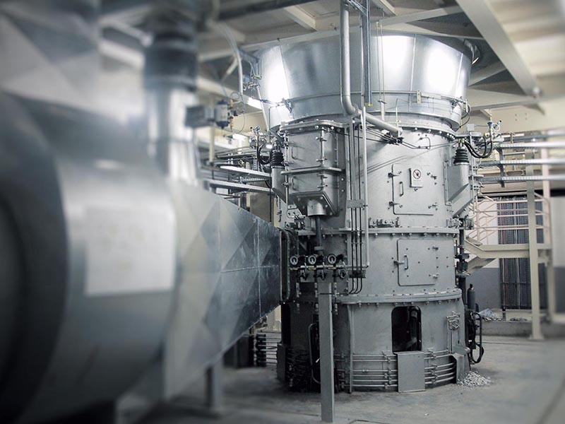
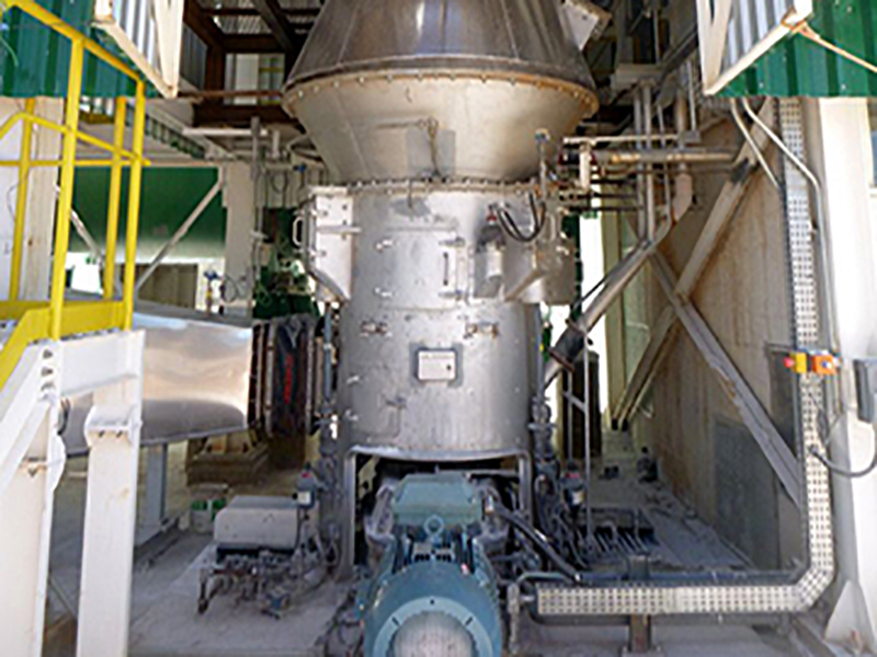
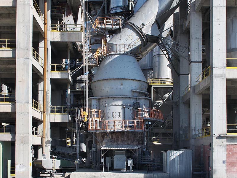
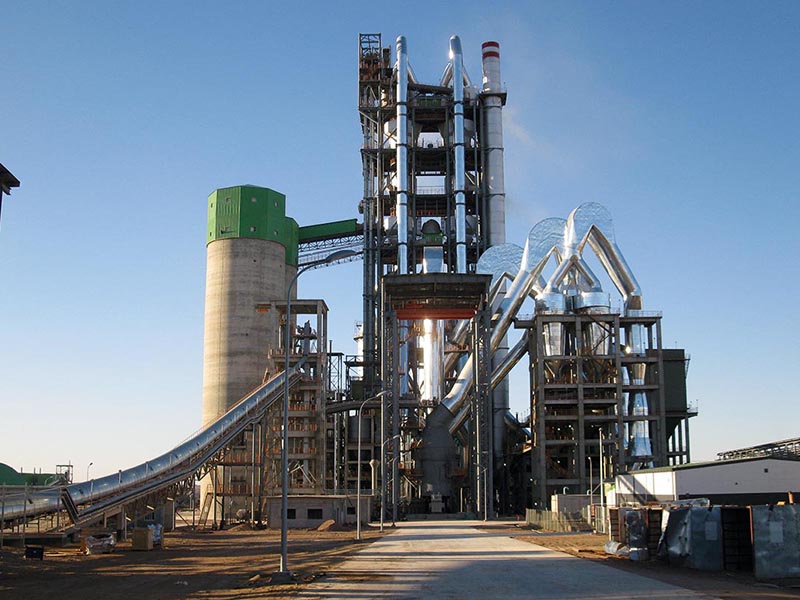
The versatile MPS vertical mill – with a fine tradition of quality grinding
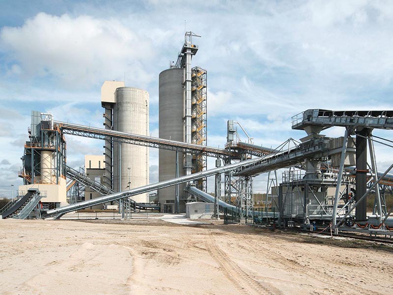
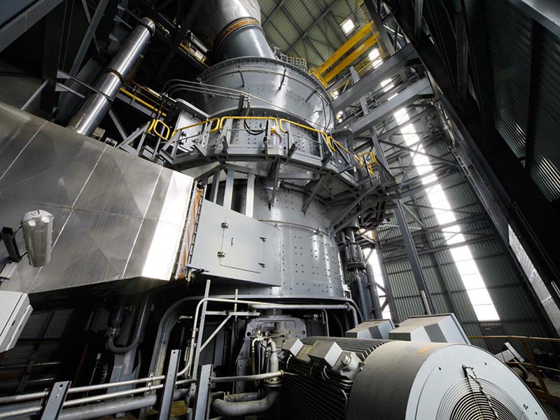
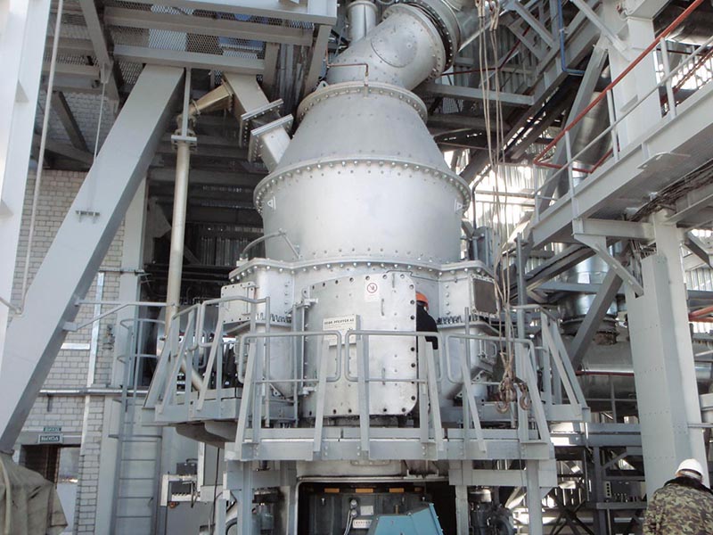
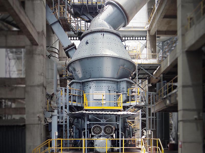
Highest flexibility with constant product quality, individually conceived, suitable for a variety of applications, undergoing constant development: with a number of more than 2800 mills sold, the MPS vertical mill is our proven allrounder. It can be used for the grinding of coal, petcoke, clay, limestone, quicklime and many other materials no matter how different their grindability and abrasiveness may be or whatever fineness or drying degree is required. The MPS mill also grinds, dries, calcines, and classifies gypsum without any problem, all in a single machine, for any fineness requested and considering individual requirements. The MPS vertical roller mill - built to last, reliable and energy-efficient - is the optimum solution when it comes to performing several process steps in one unit.
Low capital expenditure
MPS mills need only few peripheral machinery, no or little walled-in space, their operation is dust-free and they have a low noise level.
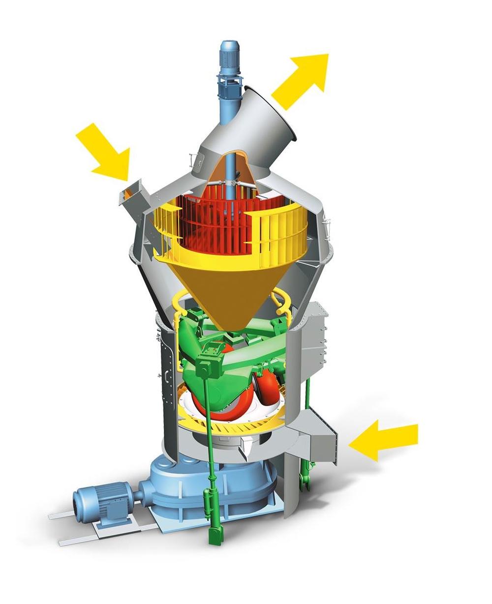
| F | Fines |
| M | Material to be ground |
| H | Hot gases |
| 1 | SLS high efficiency classifier for sharp separation |
| 2 | Closed mill housing pressure-shock proof up to 3.5 bar |
| 3 | Optimized free flow areas |
| 4 | Maintenance door with Lift-and-Swing System |
| 5 | Design measures preventing pulverized coal deposits |
| 6 | Rollers can be lifted off |
| 7 | Pull rods outside mill housing |
Activate the markers for further information
Working principle
Three stationary grinding rollers roll on a rotating grinding table. The material is drawn in between the rollers and grinding table and ground by pressure and shear. The required pressure forces are produced by a hydropneumatic tension system. After being rolled over by the rollers, the material is conveyed to a stationary nozzle ring due to the rotation of the grinding table. Gases (air or hot gas) flow through this nozzle ring, take up the ground and dried material and convey it to the classifier where it is separated by the rotating wheel (rotor) into grits and fines. The grits fall back into the grinding zone whereas the fines leave the classifier with the gas flow for being separated in cyclones or a filter.
| Technical data | |
|---|---|
| Throughput rate | up to 110 t/h |
| Mill drive | up to 2,000 kW |
| Number of grinding rollers | 3 |
| Feed size | up to 100 mm |
| Feed moisture | up to 35% (surface moisture) |
| Target fineness degrees | 60 - 100 µm |
| Classifier | high efficiency classifier |
| Grinding table diameter | up to 4,500 mm |
| Pressure-shock proof | up to 3.5 bar |
| Feed material | coal, petcoke |
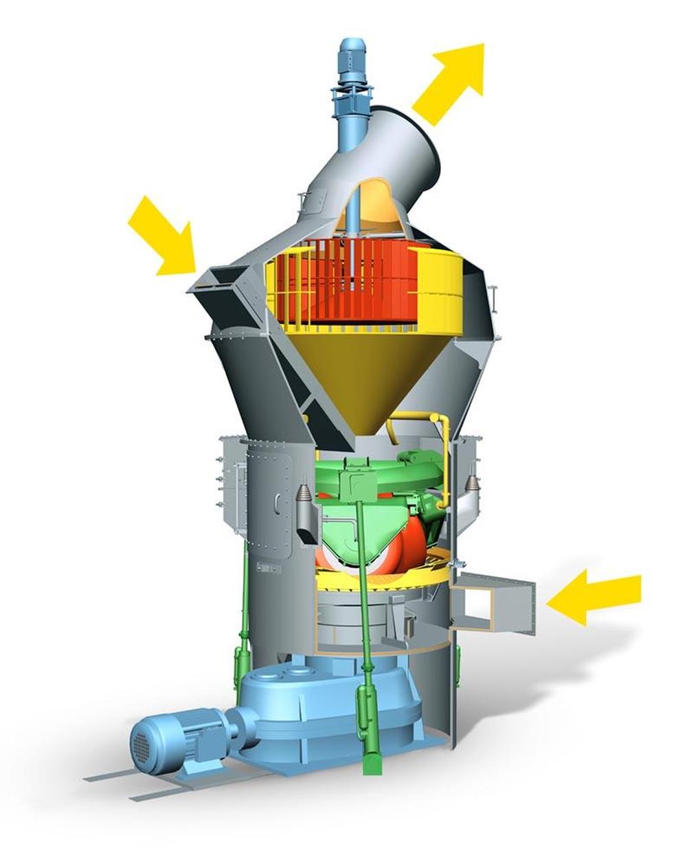
| F | Fines |
| M | Material to be ground |
| H | Hot gases |
| 1 | SLS high efficiency classifier for sharp separation |
| 2 | Closed mill housing |
| 3 | Optimized free flow areas |
| 4 | Maintenance door with Lift-and-Swing System |
| 5 | Rollers can be lifted off |
| 6 | Pull rods outside mill housing |
| 7 | Nozzle ring centering in case of grinding-calcining |
| 8 | Insulation of hot gas area in case of grinding-calcining |
Activate the markers for further information
Working principle
Three stationary grinding rollers roll on a rotating grinding table. The material is drawn in between the rollers and grinding table and ground by pressure and shear. The required pressure forces are produced by a hydropneumatic tension system. After being rolled over by the rollers, the material is conveyed to a stationary nozzle ring due to the rotation of the grinding table. Gases (air or hot gas) flow through this nozzle ring, take up the ground and dried material and convey it to the classifier where it is separated by the rotating wheel (rotor) into grits and fines. The grits fall back into the grinding zone whereas the fines leave the classifier with the gas flow for being separated in cyclones or a filter.
| Technical Data | |
|---|---|
| Throughput rate | up to 150 t/h |
| Number of grinding rollers | 3 |
| Feed size | up to 60 mm |
| Feed moisture | pit moisture |
| Target fineness degrees | 60 - 500 µm |
| Classifier | high efficiency classifier |
| Feed material | natural gypsum, mixtures of natural gypsum and FGD gypsum |
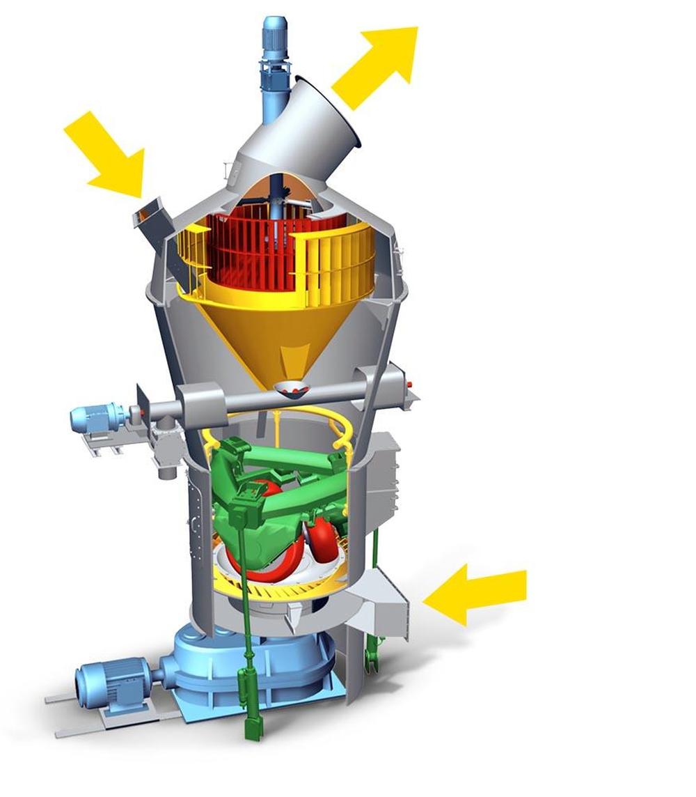
| F | Fines |
| M | Material to be ground |
| H | Hot gases |
| 1 | SLS high efficiency classifier for sharp separation |
| 2 | Closed mill housing |
| 3 | Optimized free flow areas |
| 4 | Discharge of adverse ingredients as an option |
| 5 | Maintenance door with Lift-and-Swing System |
| 6 | Rollers can be lifted off |
| 7 | Pull rods outside mill housing |
Activate the markers for further information
Working principle
Three stationary grinding rollers roll on a rotating grinding table. The material is drawn in between the rollers and grinding table and ground by pressure and shear. The required pressure forces are produced by a hydropneumatic tension system. After being rolled over by the rollers, the material is conveyed to a stationary nozzle ring due to the rotation of the grinding table. Gases (air or hot gas) flow through this nozzle ring, take up the ground and dried material and convey it to the classifier where it is separated by the rotating wheel (rotor) into grits and fines. The grits fall back into the grinding zone whereas the fines leave the classifier with the gas flow for being separated in cyclones or a filter.
| Technical data | |
|---|---|
| Throughput rate | up to 200 t/h |
| Number of grinding rollers | 3 |
| Feed size | up to 60 mm |
| Feed moisture | pit moisture |
| Target fineness degrees | 20 - 500 µm |
| Finished product moisture | < 1% H2O |
| Classifier | high efficiency classifier |
| Feed material | clay, bentonite |
| Optional discharge of adverse ingredients (e.g. pyrite) | |
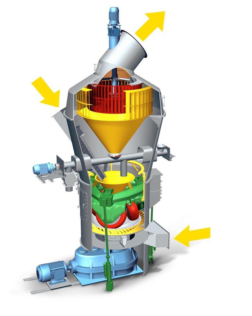
| F | Fines |
| M | Material to be ground |
| H | Hot gases |
| 1 | SLS high efficiency classifier for sharp separation |
| 2 | Closed mill housing |
| 3 | Optimized free flow areas |
| 4 | Discharge of adverse ingredients as an option |
| 5 | Maintenance door with Lift-and-Swing System |
| 6 | Rollers can be lifted off |
| 7 | Pull rods outside mill housing |
Activate the markers for further information
Working principle
Three stationary grinding rollers roll on a rotating grinding table. The material is drawn in between the rollers and grinding table and ground by pressure and shear. The required pressure forces are produced by a hydropneumatic tension system. After being rolled over by the rollers, the material is conveyed to a stationary nozzle ring due to the rotation of the grinding table. Gases (air or hot gas) flow through this nozzle ring, take up the ground and dried material and convey it to the classifier where it is separated by the rotating wheel (rotor) into grits and fines. The grits fall back into the grinding zone whereas the fines leave the classifier with the gas flow for being separated in cyclones or a filter.
| Technical data | |
|---|---|
| Throughput rate | up to 200 t/h |
| Mill drive | up to 2,000 kW |
| Number of grinding rollers | 3 |
| Feed size | up to 100 mm |
| Feed moisture | up to 10% |
| Target fineness degree of fine material | up to 30 µm |
| Target fineness degree of discharged coarse material | up to 2 mm |
| Classifier | high efficiency classifier |
| Grinding table diameter | up to 4,500 mm |
| Feed material | limestone |
| With or without coarse material discharge | |

| F | Fines |
| M | Material to be ground |
| H | Hot gases |
| 1 | SLS high efficiency classifier for sharp separation |
| 2 | Closed mill housing |
| 3 | Optimized free flow areas |
| 4 | Maintenance door with Lift-and-Swing System |
| 5 | Rollers can be lifted off |
| 6 | Pull rods outside mill housing |
Activate the markers for further information
Working principle
Three stationary grinding rollers roll on a rotating grinding table. The material is drawn in between the rollers and grinding table and ground by pressure and shear. The required pressure forces are produced by a hydropneumatic tension system. After being rolled over by the rollers, the material is conveyed to a stationary nozzle ring due to the rotation of the grinding table. Gases (air or hot gas) flow through this nozzle ring, take up the ground and dried material and convey it to the classifier where it is separated by the rotating wheel (rotor) into grits and fines. The grits fall back into the grinding zone whereas the fines leave the classifier with the gas flow for being separated in cyclones or a filter.
| Technical data | |
|---|---|
| Throughput rate | up to 80 t/h |
| Mill drive | up to 600 kW |
| Number of grinding rollers | 3 |
| Feed size | up to 60 mm |
| Target fineness | up to 20 µm |
| Classifier | high efficiency classifier |
| Feed material | quicklime |

| F | Fines |
| M | Material to be ground |
| H | Hot gases |
| 1 | SLS high efficiency classifier for sharp separation |
| 2 | Closed mill housing |
| 3 | Optimized free flow areas |
| 4 | Maintenance door with Lift-and-Swing System |
| 5 | Rollers can be lifted off |
| 6 | Pull rods outside mill housing |
Activate the markers for further information
Working principle
Three stationary grinding rollers roll on a rotating grinding table. The material is drawn in between the rollers and grinding table and ground by pressure and shear. The required pressure forces are produced by a hydropneumatic tension system. After being rolled over by the rollers, the material is conveyed to a stationary nozzle ring due to the rotation of the grinding table. Gases (air or hot gas) flow through this nozzle ring, take up the ground and dried material and convey it to the classifier where it is separated by the rotating wheel (rotor) into grits and fines. The grits fall back into the grinding zone whereas the fines leave the classifier with the gas flow for being separated in cyclones or a filter.
| Technical data | |
|---|---|
| Throughput rate | up to 200 t/h |
| Mill drive | up to 2,000 kW |
| Number of grinding rollers | 3 |
| Feed size | up to 100 mm |
| Feed moisture | up to 10% |
| Target fineness degrees | 30 µm |
| Classifier | high efficiency classifier |
| Grinding table diameter | up to 4,500 mm |
| Feed material | kaolin, talc, pozzolana and many more |
Wear protection/maintenance
Depending on the abrasiveness of the material to be ground and areas to be protected, different wear materials are used on our vertical roller mills. The grinding elements are primarily made of alloy cast iron as per DIN 1695, hardfaced cast iron or composite materials with high-chromium inserts in ductile base materials. The housings and other mill components are protected against jet wear with highly wear-resistant steel plates or hardfaced composite plates. Components which are specifically exposed to wear like gas outlet ducts have additional ceramic liners. All this is for optimum protection and short maintenance shutdown.
Swing-out system of rollers on MPS mills
The highest wear occurs on the wear parts of the grinding elements as is the case with any type of vertical mill. Therefore, ease of replacement and regeneration is a major feature of the mill. With our proven Lift-and-Swing System, wear parts can be replaced rapidly through one single maintenance door. The grinding rollers and grinding table segments are driven to the maintenance door with the maintenance drive and are swung out of the grinding area. As a result maintenance downtime is reduced and work is easy and safe.


