For extra-large throughput rates: MVR vertical mill with multiple drive
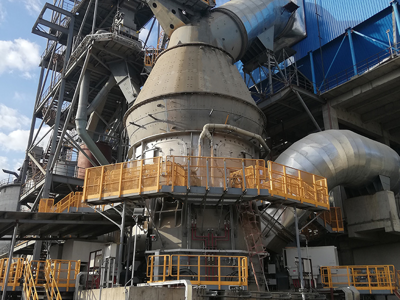
High throughput rates, permanent plant availability , optimized maintenance concepts – features of the MVR mill and the patented MultiDrive® enabling Gebr. Pfeiffer to meet the ever rising expectations of the industry. Thanks to the innovative drive and active redundancy, an unintended stop of the grinding process is practically excluded. No matter what type of material has to be ground – cement raw material, cement clinker or granulated blast-furnace slag – and how different their grindability and abrasiveness may be, the MVR mill ensures throughput rates of a different dimension, around the clock, reliably and on the long term. Forget about downtime. With Pfeiffer you will grind on a grand scale.
Throughput rates of more than 1,400 t/h on a single mill
Owing to the MultiDrive® specially conceived for the Pfeiffer MVR mill, two mills equipped with conventional drives can be replaced with just one mill. Learn more about the Pfeiffer MultiDrive®
Highest availability thanks to double active redundancy, i.e. for grinding rollers and drive modules
An MVR mill may have up to six grinding rollers and up to six drive units. Thus both systems are actively redundant meaning that one or several rollers can be taken out of the system for maintenance work while mill operation continues. The same applies to the independent drive modules of the MultiDrive®.
Low capital expenditure
MVR mills need only few peripheral machinery, no or little walled-in space, their operation is dust-free and they have a low noise level.
Optimum utilization of process heat
The thermal energy of process gases can be used on Pfeiffer roller mills.
Favorable control behavior
High drying capacity, short dwell time of the material to be ground, and remote control of grinding pressure and classifier rotor speed ensure a fully automatic operation of the MVR mill even with varying raw material characteristics.
Homogeneous compaction of the material to be ground
Thanks to the geometry of the grinding rollers in combination with their specific suspension, there is always a parallel grinding gap, ensuring a homogeneous compaction of the material to be ground. Moreover, due to the symmetric shape of the grinding roller tires, these can be turned when worn.

| F | Fines |
| M | Material to be ground |
| H | Hot gases |
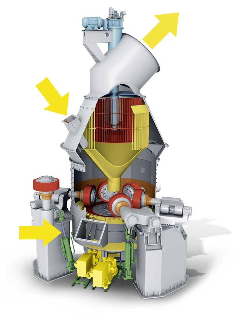
| 1 | SLS high efficiency classifier for sharp separation |
| 2 | Optimized free flow areas |
| 3 | Rollers can be swung out separately with hydraulic system, for operation with n-1 rollers |
| 4 | Rollers can be lifted off |
| 5 | Parallel grinding gap |
| 6 | Space-saving twin support for largest possible maintenance access |
| 7 | Up to six MultiDrive® modules ensuring active redundancy |
| 8 | Drive modules can be pulled out separately for operation with n-1 drive modules |
Activate the markers for further information
Working principle
Up to six stationary grinding rollers roll on a rotating grinding table. The material is drawn in between the rollers and grinding table and ground by pressure and shear. The required pressure forces are produced by a lever system comprising, among others, a roller arm, along with a hydropneumatic tension system. After being rolled over by the rollers, the material is conveyed to a stationary nozzle ring due to the rotation of the grinding table. Gases (air or hot gas) flow through this nozzle ring, take up the ground and dried material and convey it to the classifier where it is separated by the rotating wheel (rotor) into grits and fines. The grits fall back into the grinding zone whereas the fines leave the classifier with the gas flow for being separated in cyclones or a filter.
| Technical data | |
|---|---|
| Throughput rate | up to 550 t/h |
| Mill drive | up to 18,000 kW |
| Number of grinding rollers | up to 6 |
| Feed size | up to 120 mm |
| Target fineness degrees | 1,500 – 6,000 cm2/g |
| Classifier | high efficiency classifier |
| Grinding table diameter | up to 6,700 mm |

| F | Fines |
| M | Material to be ground |
| H | Hot gases |
| 1 | SLS high efficiency classifier for sharp separation |
| 2 | Optimized free flow areas |
| 3 | Rollers can be swung out separately with hydraulic system, for operation with n-1 rollers |
| 4 | Rollers can be lifted off |
| 5 | Parallel grinding gap |
| 6 | Space-saving twin support for largest possible maintenance access |
| 7 | Up to six MultiDrive® modules ensuring active redundancy |
| 8 | Drive modules can be pulled out separately for operation with n-1 drive modules |
Activate the markers for further information
Working principle
Up to six stationary grinding rollers roll on a rotating grinding table. The material is drawn in between the rollers and grinding table and ground by pressure and shear. The required pressure forces are produced by a lever system comprising, among others, a roller arm, along with a hydropneumatic tension system. After being rolled over by the rollers, the material is conveyed to a stationary nozzle ring due to the rotation of the grinding table. Gases (air or hot gas) flow through this nozzle ring, take up the ground and dried material and convey it to the classifier where it is separated by the rotating wheel (rotor) into grits and fines. The grits fall back into the grinding zone whereas the fines leave the classifier with the gas flow for being separated in cyclones or a filter.
| Technical data | |
|---|---|
| Throughput rate | up to 1,400 t/h |
| Mill drive | up to 18,000 kW |
| Number of grinding rollers | up to 6 |
| Feed size | up to 120 mm |
| Feed moisture | bis 20 % |
| Target fineness degree | 60 – 100 µm |
| Classifier | high efficiency classifier |
| Grinding table diameter | up to 6,700 mm |
| Gas flow rates | bis 2.200.000 m³/h |

| F | Fines |
| M | Material to be ground |
| H | Hot gases |
| 1 | SLS high efficiency classifier for sharp separation |
| 2 | Optimized free flow areas |
| 3 | Rollers can be swung out separately with hydraulic system, for operation with n-1 rollers |
| 4 | Rollers can be lifted off |
| 5 | Parallel grinding gap |
| 6 | Space-saving twin support for largest possible maintenance access |
| 7 | Up to six MultiDrive® modules ensuring active redundancy |
| 8 | Drive modules can be pulled out separately for operation with n-1 drive modules |
Activate the markers for further information
Working principle
Up to six stationary grinding rollers roll on a rotating grinding table. The material is drawn in between the rollers and grinding table and ground by pressure and shear. The required pressure forces are produced by a lever system comprising, among others, a roller arm, along with a hydropneumatic tension system. After being rolled over by the rollers, the material is conveyed to a stationary nozzle ring due to the rotation of the grinding table. Gases (air or hot gas) flow through this nozzle ring, take up the ground and dried material and convey it to the classifier where it is separated by the rotating wheel (rotor) into grits and fines. The grits fall back into the grinding zone whereas the fines leave the classifier with the gas flow for being separated in cyclones or a filter.
| Technical data | |
|---|---|
| Throughput rate | up to 7,000 t/h |
| Mill drive | up to 18,000 kW |
| Number of grinding rollers | up to 6 |
| Feed size | up to 175 mm |
| Range of grind size / product size | P80 = 1 mm down to P99 = 20 µm |
| Classifier | high efficiency classifier |
| Grinding table diameter | up to 6,700 mm |
Wear protection/maintenance
Depending on the abrasiveness of the material to be ground and areas to be protected, different wear materials are used on our vertical roller mills. Alloy cast iron as per DIN 1695, hardfaced cast iron or composite materials with high-chromium inserts in ductile base materials: the grinding elements designed by Pfeiffer are made of high-quality materials ensuring a long lifetime. The housings and other mill components, too, are protected against wear with highly wear-resistant steel plates or hardfaced composite plates. Components which are specifically exposed to wear like gas outlet ducts have additional ceramic liners. All this is for optimum protection and short maintenance shutdown.
Swing-out system of rollers on MVR mills
The highest wear occurs on the wear parts of the grinding elements as is the case with any type of vertical mill. Therefore, ease of replacement and regeneration is a major feature of the mill. The MVR mill has a modern hydraulic system used in operation and for maintenance alike. With this new type of roller suspension, the rollers can be swung out of the mill in a controlled way – for ease of replacing the one-part grinding roller tires. The segmented wear parts of the grinding table are replaced, using a lifting device and the maintenance drive. Moreover, the rollers can be swung out separately. Hence grinding operation can be continued while maintenance work is done. The parts concerned can be regenerated both inside the mill and outside. Forget about downtime and maintenance problems! With active redundancy and easy maintenance you are up to date!


